How to improve circuitikz single line diagrams?
TeX - LaTeX Asked on June 23, 2021
I have come quite far with circuitikz in drawing good looking single-line diagrams. There are however a few possible improvements.
Here are my result so far ( and the code is added below.) The example might be a bit cluttered but it is easier to remove unwanted elements later:

The following can be improved:
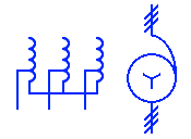
delta,wyeandzigsymbols are too small and inconsistent thickness, compare withvco- there is no three-phase autotransformer symbol (rhs symbol rotated +j and without the three-line symbols)
- the
busbarsof length 0.3 with the label can be included as a symbol - the
osourcetranssymbols should be scaled up 1/0.55 to be consistent with the other symbols (I still need to implement this in the source) - the
osourcetranslabels are not correctly positioned and can be improved to include multiple lines as indicated - the grounding symbols:
psolid,pres,pimp,parc,ssolid,sres,simporsarccan be added
Any suggestions will be appreciated.
documentclass[beamer]{standalone}
usepackage{tikz}
defpgfsysdriver{pgfsys-dvipdfm.def}
%
usepackage{pgfplots}
usepackage[siunitx,european,oldvoltagedirection]{circuitikz}
usepackage{xspace}
usepackage{comment}


%renewcommand*familydefault{sfdefault} %% Only if the base font of the document is to be sans serif
usepackage[T1]{fontenc}
usepackage{lmodern}
usepackage{bm}

usepackage{amsmath}
usepackage{steinmetz}
usepackage{pgf,siunitx}
sisetup{output-decimal-marker = {,}
,separate-uncertainty}
SendSettingsToPgf
%
usepackage{relsize}


%usepackage{longtable}
%usepackage{lscape}


usepackage[iso,english]{isodate}
%renewcommand*date[1]{{isodate{#1}}}

usepackage{steinmetz}% for phasor{t}

usepackage[UKenglish]{babel}


pgfplotsset{width=11cm, height=6cm, compat = 1.7}
usetikzlibrary{calc,angles,quotes}
makeatother
usepackage[subpreambles=true]{standalone}
usepackage{import}

begin{document}
{hfillsmallbegin{circuitikz}[style={european resistor, resistors/scale=0.55, inductors/scale=0.55, blocks/scale=0.5, grounds/scale=0.55}]
 draw (0,0)
 to [vco,-,v>=SI{24}{kV},l=$G$] ++(1,0)
 to[oosourcetrans,name=t1,prim=delta,sec=wye,-,] ++(1.5,0)
 -- ++(0,0.6)
 to [L,-,l=$Z_1$] ++(1,0)
 to [L,-,l=$Z_2$] ++(1,0)
 -- ++(0,-0.6)
 to[oosourcetrans,name=t2,prim=wye,sec=zig,-,] ++(1.5,0)
 to [L,-,l=$Z_c$] ++(1,0)
 to[oosourcetrans,name=t3,prim=delta,sec=wye,-,] ++(1.5,0)
 to [R,-,l=$R_text{load}$,] ++(1,0)
 ;
 % fixing the labels of oosourcetrans to correct the distance from the symbol
 draw (t1.90) ++(0,0.15) node {shortstack{$T_1$$_{24:132}$}};
 draw (t2.90) ++(0,0.15) node {shortstack{$T_2$$_{132:12}$}};
 draw (t3.90) ++(0,0.15) node {shortstack{$T_3$$_{12:num{0.4}}$}};
 % add the correct earthing symbols to the oosourcetrans
 draw (t1.-70)  ++(0,0.2) node[ground]{};
 draw (t2.-70)  ++(0,0.2) to [R,-,resistors/scale=0.3,l={scriptsize SI{1.5}{kiloampere}}] ++(0,-0.6) node[tlground]{};
 draw (t2.-110)  ++(0,0.2) node[ground]{};
 draw (t3.-70)  ++(0,0.2) node[ground]{};
% draw and label busbars (busbars are vertical with length = 0.6)
 draw [ultra thick] (2.5,-0.9) -- ++(0,1.8)node [anchor=south] {$gs_1$}; % generation station busbar
 draw [ultra thick] (3.5,0.3) -- ++(0,0.6)node [anchor=south] {$ts_1$}; % transmission station busbar
 draw [ultra thick] (4.5,-0.9) -- ++(0,1.8)node [anchor=south] {$ds_1$}; % transmission station busbar
 draw [ultra thick] (6,-0.3) -- ++(0,0.6) node [anchor=south] {$ds_2$}; % distribution station busbar
 draw [ultra thick] (7,-0.3) -- ++(0,0.6) node [anchor=south] {$ms_1$}; % minisub
 draw (2.5,-0.6) to [L,-,l=$Z_3$, v=$Delta U_t$] ++(2,0);
end{circuitikz}hfill~}
end{document}
One Answer
Ok, I'll try to answer some of this. Let's start with the list of questions (please, next time, one question per post).
- Yes, that is true --- I will contact the author to see if we can add a switch/parameter for this (Update: it will be in the next release). For now, I propose a brute-force patch of the symbols.
- You can make a new symbol request on https://github.com/circuitikz/circuitikz/issues, with references to printed things, and maybe somebody will do it (or you could try a go at it! You'll be welcome!)
- I propose using a macro, like in https://tex.stackexchange.com/a/597815/38080, but I provide a
buselement here if you prefer thetosyntax. - You were using a non-standard way of setting relative size, try again!
- I provide two example for positioning a multi-line label, either using the provide
l2facility, or withshortstackand adjusting the distance; - I do not know how all those "ground styles" are. Please see point 2.
Now, the code does the following (I have put comments in it; notice that this is a minimal example, so I can work on it and not having tons of repetitions and distracting things...)
It starts patching the commands
pgf@circ@delta, etc., that are used to draw the transformers' symbols. You can find them inpgfcircbipoles.texin your distribution. The first three resets the linewidth to the standard one for the circuit, the second three change the size a bit.I define a bus as a very squeezed
fullgeneric, with a parameter for the height, and a default of3(you can change this; the number are all proportional to the standard length)If you do not want poles, no need to use
-in everytocommand, it's the default.There are two ways to position the label; using
l2is more spacy (and in my opinion readable), usingstackengineis more compact --- a matter of tastes, I suppose.
documentclass[border=10pt]{standalone}
usepackage[siunitx, RPvoltages]{circuitikz}
usepackage{etoolbox}

makeatletter
% This should probably be added as a couple of parameters; I'll contact the author
% (see https://github.com/circuitikz/circuitikz/pull/397). But for now, let's just patch
% patching linewidth
patchcmd{pgf@circ@delta}
    {pgf@circ@setlinewidth{bipoles}{pgfstartlinewidth}}
    {pgfsetlinewidth{pgfstartlinewidth}}
    {}{FAIL}
patchcmd{pgf@circ@zig}
    {pgf@circ@setlinewidth{bipoles}{pgfstartlinewidth}}
    {pgfsetlinewidth{pgfstartlinewidth}}
    {}{FAIL}
patchcmd{pgf@circ@wye}
    {pgf@circ@setlinewidth{bipoles}{pgfstartlinewidth}}
    {pgfsetlinewidth{pgfstartlinewidth}}
    {}{FAIL}
% patching scale
patchcmd{pgf@circ@delta}{-.01}{-.02}{}{FAIL}
patchcmd{pgf@circ@wye}{-.015}{-.02}{}{FAIL}
patchcmd{pgf@circ@zig}{-.015}{-.02}{}{FAIL}
makeatother

% define the bus (ab-)using the fullgeneric component
%
tikzset{bus/.style={fullgeneric, %
        bipoles/fullgeneric/width=0.02, bipoles/fullgeneric/height=#1
    },
    bus/.default=3
}
begin{document}
begin{circuitikz}[european] % do not use style={}!
    % this is the correct way to set the class values
    ctikzset{resistors/scale=0.55, inductors/scale=0.55,
         blocks/scale=0.5, grounds/scale=0.55}
    draw (0,0)
    % choose one of the following two
    % to[oosourcetrans, name=t1, prim=delta, sec=wye,
    %     l=shortstack{$T_1$${}_{24:132}$}, label distance=-6pt] ++(3,0)
    to[oosourcetrans, name=t1, prim=delta, sec=wye,
        l2=$T_1$ and {scriptsize 24:132}, l2 halign=c] ++(3,0)
    to[bus, l=$gs_1$, name=gs1] ++(1,0)
    (gs1.center) ++(0, 0.6) to [L,l=$Z_1$] ++(2,0)
    to [bus=1, l=$ts_1$] ++(1,0);
end{circuitikz}
end{document}

PS You can notice why I prefer the macro for the bus: using the macro, as in the linked post, the bus has a zero width, so that the components between buses are naturally centered. If you use a to[bus... syntax, the component has the size of the path, and you have to take into account the distances by yourself, and you have to manage the leading wires. If you use the definition in https://tex.stackexchange.com/a/597815/38080, the circuit will be:
begin{circuitikz}[european] % do not use style={}!
    % this is the correct way to set the class values
    ctikzset{resistors/scale=0.55, inductors/scale=0.55,
        blocks/scale=0.5, grounds/scale=0.55}
    draw (0,0)
    % choose one of the following two
    % to[oosourcetrans, name=t1, prim=delta, sec=wye,
    %     l=shortstack{$T_1$${}_{24:132}$}, label distance=-6pt] ++(3,0)
    to[oosourcetrans, name=t1, prim=delta, sec=wye,
        l2=$T_1$ and {scriptsize 24:132}, l2 halign=c] ++(3,0)
    bushere{1.5}{$gs_1$}{}
    ++(0, 0.6) to [L,l=$Z_1$] ++(2,0)
    bushere{0.5}{$ts_1$}{};
end{circuitikz}
with this result:

PPS yes, the buses are a bit asymmetric. This is due to a bug in bushere that makes space for the upper label... the solution (any one of them) is left to the student!
Correct answer by Rmano on June 23, 2021
Add your own answers!
Ask a Question
Get help from others!
Recent Answers
- Joshua Engel on Why fry rice before boiling?
- Lex on Does Google Analytics track 404 page responses as valid page views?
- haakon.io on Why fry rice before boiling?
- Peter Machado on Why fry rice before boiling?
- Jon Church on Why fry rice before boiling?
Recent Questions
- How can I transform graph image into a tikzpicture LaTeX code?
- How Do I Get The Ifruit App Off Of Gta 5 / Grand Theft Auto 5
- Iv’e designed a space elevator using a series of lasers. do you know anybody i could submit the designs too that could manufacture the concept and put it to use
- Need help finding a book. Female OP protagonist, magic
- Why is the WWF pending games (“Your turn”) area replaced w/ a column of “Bonus & Reward”gift boxes?